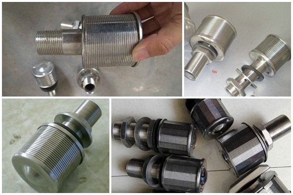
| Category: | Water Strainer & Nozzle |
| Material: | stainless steel 304,304L,304HC,316,316L,321,430 or as per your request |
| Properties: | wedge wire screen |
| Application: | water-treatment, water well drilling ,oil well drilling ,mineral processing, coal-cleaning plant |
SS wedge wire sand control filter nozzles are used in liquid/solid or gas/solid separation (sand, catalyst, resins, zeolite etc). The design of each nozzle and the exact quantity will be proposed in order to obtain a perfect distribution or collection of flow.
Our filter nozzles are an excellent technical and economical solution in bringing together a fully welded, strong and highly corrosion resistant structure and with a non-plugging surface.

1) Type 316L stainless steel construction.
2) Continuous slot design provides increased open area for better collection.
3) Standard nozzles are 2in./51mm diameter and can be attached to the plate either with threaded end fittings or with“L”bolts.
4) Standard slot opening is typically range between 0.006”(0.15mm), and 0.020in./0.50mm wide suitable for 40 to 50 mesh size media, Other slot sizes are also available.
5) Wedge wire screen is highly resistant to plugging.
6) Choice of either 3/4”NPT or 1”NPT fittings are available from stock. Other styles, such as tee-bolt mountings, and drop tubes are readily available.
7) Less expensive than other screen of equal efficiency.
used widely in down-flow reactors for liquid/solid or gas/solid separation. The liquid or gas can flow through the nozzles while the solids are retained in the vessel by the nozzles.
The height of a nozzle and the internal diameter of the fitting can be approximated using the following graphs.
Slot entrance velocity nominally 0.2m/s (to be optimised dependant upon the filter media)
By optimising the ratio between the head loss of each component (open area and fitting) we can determine the optimum quantity of nozzles to ensure a perfect distribution or collection without channelling, wall effects, or dead zones.

|
Type |
Slot |
Dimension |
Flow area |
|||
|
D |
H |
L |
M |
|||
|
A |
0.25 |
Φ45 |
40 |
90 |
M20 |
450m3 |
|
A1 |
0.25 |
Φ45 |
40 |
90 |
M24 |
500m3 |
|
(flow 0.5T/H) |
||||||
|
B |
0.25 |
Φ53 |
45 |
100 |
M24 |
570m3 |
|
(flow 1T/H) |
||||||
|
B1 |
0.25 |
Φ53 |
45 |
100 |
M32 |
600m3 |
|
(flow 1.5T/H) |
||||||
|
B3 |
0.25 |
Φ57 |
55 |
110 |
M32 |
800m3 |
|
(flow 2T/H) |
||||||
|
C |
0.2-0.5 |
Φ70 |
45 |
110 |
M32 |
800m3 |
|
C1 |
0.2-0.5 |
Φ70 |
55 |
120 |
M32 |
1000m3 |
